Antenna Theory- Parameters
The basic communication parameters are discussed in this chapter to have a better idea about the wireless communication using antennas. The wireless communication is done in the form of waves. Hence, we need to have a look at the properties of waves in the communications.
In this chapter, we are going to discuss about the following parameters −
- Frequency
- Wavelength
- Impedance matching
- VSWR & reflected power
- Bandwidth
- Percentage bandwidth
- Radiation intensity
Now, let us learn them in detail.
Frequency
According to the standard definition, “The rate of repetition of a wave over a particular period of time, is called as frequency.”
Simply, frequency refers to the process of how often an event occurs. A periodic wave repeats itself after every ‘T’ seconds (time period). Frequency of periodic wave is nothing but the reciprocal of time period (T).
Mathematical Expression
Mathematically, it is written as shown below.
Where
f is the frequency of periodic wave.
T is the time period at which the wave repeats.
Units
The unit of frequency is Hertz, abbreviated as Hz.
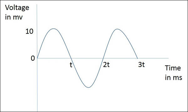
The figure given above represents a sine wave, which is plotted here for Voltage in millivolts against time in milliseconds. This wave repeats after every 2t milliseconds. So, time period, T=2t milliseconds and frequency,
Wavelength
According to the standard definition, “The distance between two consecutive maximum points (crests) or between two consecutive minimum points (troughs) is known as the wavelength.”
Simply, the distance between two immediate positive peaks or two immediate negative peaks is nothing but the length of that wave. It can be termed as the Wavelength.
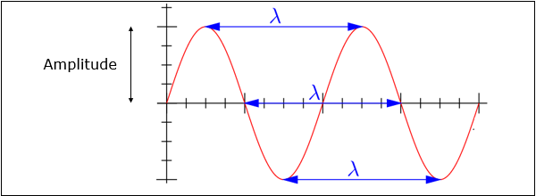
The following figure shows a periodic waveform. The wavelength (λ) and amplitude are denoted in the figure. The higher the frequency, the lesser will be the wavelength and vice versa.
Mathematical Expression
The formula for wavelength is,
Where
λ is the wavelength
c is the speed of light ( meters/second)
f is the frequency
Units
The wavelength λ is expressed in the units of length such as meters, feet or inches. The commonly used term is meters.
Impedance Matching
According to the standard definition, “The approximate value of impedance of a transmitter, when equals the approximate value of the impedance of a receiver, or vice versa, it is termed as Impedance matching.”
Impedance matching is necessary between the antenna and the circuitry. The impedance of the antenna, the transmission line, and the circuitry should match so that maximum power transfer takes place between the antenna and the receiver or the transmitter.
Necessity of Matching
A resonant device is one, which gives better output at certain narrow band of frequencies. Antennas are such resonant devices whose impedance if matched, delivers a better output.
The power radiated by an antenna, will be effectively radiated, if the antenna impedance matches the free space impedance.
For a receiver antenna, antenna’s output impedance should match with the input impedance of the receiver amplifier circuit.
For a transmitter antenna, antenna’s input impedance should match with transmitter amplifier’s output impedance, along with the transmission line impedance.
Units
The unit of impedance (Z) is Ohms.
VSWR & Reflected Power
According to the standard definition, “The ratio of the maximum voltage to the minimum voltage in a standing wave is known as Voltage Standing Wave Ratio.”
If the impedance of the antenna, the transmission line and the circuitry do not match with each other, then the power will not be radiated effectively. Instead, some of the power is reflected back.
The key features are −
The term, which indicates the impedance mismatch is VSWR.
VSWR stands for Voltage Standing Wave Ratio. It is also called as SWR.
The higher the impedance mismatch, the higher will be the value of VSWR.
The ideal value of VSWR should be 1:1 for effective radiation.
Reflected power is the power wasted out of the forward power. Both reflected power and VSWR indicate the same thing.
Bandwidth
According to the standard definition, “A band of frequencies in a wavelength, specified for the particular communication, is known as bandwidth.”
The signal when transmitted or received, is done over a range of frequencies. This particular range of frequencies are allotted to a particular signal, so that other signals may not interfere in its transmission.
Bandwidth is the band of frequencies between the higher and lower frequencies over which a signal is transmitted.
The bandwidth once allotted, cannot be used by others.
The whole spectrum is divided into bandwidths to allot to different transmitters.
The bandwidth, which we just discussed can also be called as Absolute Bandwidth.
Percentage Bandwidth
According to the standard definition, “The ratio of absolute bandwidth to the center frequency of that bandwidth can be termed as percentage bandwidth.”
The particular frequency within a frequency band, at which the signal strength is maximum, is called as resonant frequency. It is also called as center frequency (fC) of the band.
The higher and lower frequencies are denoted as fH and fL respectively.
The absolute bandwidth is given by- fH - fL.
To know how wider the bandwidth is, either fractional bandwidth or percentage bandwidth has to be calculated.
Mathematical Expression
The Percentage bandwidth is calculated to know how much frequency variation either a component or a system can handle.
Where
is higher frequency
is lower frequency
is center frequency
The higher the percentage bandwidth, the wider will be the bandwidth of the channel.
Radiation Intensity
“Radiation intensity is defined as the power per unit solid angle”
Radiation emitted from an antenna which is more intense in a particular direction, indicates the maximum intensity of that antenna. The emission of radiation to a maximum possible extent is nothing but the radiation intensity.
Mathematical Expression
Radiation Intensity is obtained by multiplying the power radiated with the square of the radial distance.
Where
U is the radiation intensity
r is the radial distance
Wrad is the power radiated.
The above equation denotes the radiation intensity of an antenna. The function of radial distance is also indicated as Φ.
Units
The unit of radiation intensity is Watts/steradian or Watts/radian2.
Radiation intensity of an antenna is closely related to the direction of the beam focused and the efficiency of the beam towards that direction. In this chapter, let us have a look at the terms that deal with these topics.
Directivity
According to the standard definition, “The ratio of maximum radiation intensity of the subject antenna to the radiation intensity of an isotropic or reference antenna, radiating the same total power is called the directivity.”
An Antenna radiates power, but the direction in which it radiates matters much. The antenna, whose performance is being observed, is termed as subject antenna.
Its radiation intensity is focused in a particular direction, while it is transmitting or receiving. Hence, the antenna is said to have its directivity in that particular direction.
The ratio of radiation intensity in a given direction from an antenna to the radiation intensity averaged over all directions, is termed as directivity.
If that particular direction is not specified, then the direction in which maximum intensity is observed, can be taken as the directivity of that antenna.
The directivity of a non-isotropic antenna is equal to the ratio of the radiation intensity in a given direction to the radiation intensity of the isotropic source.
Mathematical Expression
The radiated power is a function of the angular position and the radial distance from the circuit. Hence, it is expressed by considering both the terms θ and Ø.
Where
is the maximum radiation intensity of subject antenna.
is the radiation intensity of an isotropic antenna (antenna with zero losses).
Aperture Efficiency
According to the standard definition, “Aperture efficiency of an antenna, is the ratio of the effective radiating area (or effective area) to the physical area of the aperture.”
An antenna has an aperture through which the power is radiated. This radiation should be effective with minimum losses. The physical area of the aperture should also be taken into consideration, as the effectiveness of the radiation depends upon the area of the aperture, physically on the antenna.
Mathematical Expression
The mathematical expression for aperture efficiency is as follows −
where
is Aperture Efficiency.
is effective area.
is physical area.
Antenna Efficiency
According to the standard definition, “Antenna Efficiency is the ratio of the radiated power of the antenna to the input power accepted by the antenna.”
Simply, an Antenna is meant to radiate power given at its input, with minimum losses. The efficiency of an antenna explains how much an antenna is able to deliver its output effectively with minimum losses in the transmission line.
This is otherwise called as Radiation Efficiency Factor of the antenna.
Mathematical Expression
The mathematical expression for antenna efficiency is given below −
Where
is the antenna efficiency.
is the power radiated.
is the input power for the antenna.
Gain
According to the standard definition, “Gain of an antenna is the ratio of the radiation intensity in a given direction to the radiation intensity that would be obtained if the power accepted by the antenna were radiated isotropically.”
Simply, gain of an antenna takes the directivity of antenna into account along with its effective performance. If the power accepted by the antenna was radiated isotropically (that means in all directions), then the radiation intensity we get can be taken as a referential.
The term antenna gain describes how much power is transmitted in the direction of peak radiation to that of an isotropic source.
Gain is usually measured in dB.
Unlike directivity, antenna gain takes the losses that occur also into account and hence focuses on the efficiency.
Mathematical Expression
The equation of gain, G is as shown below.
Where
G is gain of the antenna.
is the antenna’s efficiency.
D is the directivity of the antenna.
Units
The unit of gain is decibels or simply dB


Comments
Post a Comment